Three-color LED driving design applications typically by adjusting current to reach the balance and maximum brightness values。In general,we using most easiest and optimal way to design the full color display technology。White balance is most single for check the combination of color。The three primary colors are red and green and blue , the three primary colors are mixed according to brightness proportion。blending after human eyes feel is pure white. Earlier CRT TV to the now LCD liquid crystal display are so constituted, LED course will mature technology copying.Chromaticity coordinates LED red, green, blue is unable to achieve the full effect of the chromatogram due to process and other reasons, and the control of the primary colors including a deviation of the brightness to achieve the white light, called the match color. When performing full-color LED display before,in order to achieve optimum brightness and the lowest cost, you should try to choose RGB luminous intensity of roughly 3: 6: 1 ratio of LED devices composed of pixels balance requires the synthesis of the three primary colors in the allocation value synthesis ,it is remains the same for pure white.merely a LED is very difficult to achieve, in order to solve this problem, in general, IC will set the current size, convenient for different batches of LED can be to achieve the same white light effectWe have synthesized color called original color; Application of the red, green, and blue color is primary called, three vertices is an ideal primary color wavelength in the chromaticity diagram。if there are deviations, the color synthesized area will be reduced, the triangle will shrink in the spectral table,from a visual point of view, the color deviation will not only reduce, as shown below.LED emitted Red, green, purple and blue light according to their different wavelength characteristics ,can be roughly divide into pure red, orange, orange, orange, yellow, green, pure green, green, blue-green, blue, violet, etc., orange , green, blue and purple , pure red, pure green, pure blue price is very cheap . Three primary colors of green is most important, because the green occupy 69% brightness white and color at the center of the transverse row of the table. Therefore when the relationship between the color of purity and price trade-offs between, green is the object of important consideration.
Category Archives: Uncategorized
LED basic knowledge quiz(part 3)
29,what is the static driver? What is the scan driver? What is the difference between the static driver and scan driver?
From the driver IC output pin to implement the pixel “point to point control” is called static drive; from drive IC output pin to implement the pixel “point to control the column” called the scanning driving, it needs the row control circuit; from the drive plate can clearly see: static drive not the need for control circuit, high cost, but the display effect is good, good stability, brightness loss is smaller; scanning drive need the row control circuit, but the cost is low, shows effect is poor, poor stability, brightness loss;
30,what is a constant current driving? What is the constant voltage driving?
Constant flow refers to the IC driver working of allows environment, the design of a constant predetermined output
current value; constant pressure refers to the IC driver
working of allows the environment, the design of a constant predetermined output voltage value;
31, what is the nonlinear Calibration?
If computer output without Verify digital signal is displayed on the LED screen will appear color distortion, so at the system control circuit, the computer will be output a signal that is via nonlinear function to counter a result, and it’s display needs.the signal will be the original computer signal output by a nonlinear function to calculate the display needs, due to the nonlinear relationship between signal, so, we often call it as nonlinear correction; due to non-linear relationship between the front and rear signals, so we often call for nonlinear Calibration;
32, what is the rated working voltage? What is the working voltage? What is the power supply voltage?
Rated working voltage refers to the voltage value during normal operation ; work with electrical voltage is within the rated voltage range, voltage value during normal operation; supply voltage divide into AC and DC supply voltage,
33,what is the color distortion?
Refer to the same object in nature and displayed on the screen, both for human sensory visual difference;
34, what is the synchronization system, what is the asynchronous system?
Synchronous and asynchronous is relative to the computer, so-called synchronization system,refers to the control system of LED display screen shows the contents and computer display the contents is asynchronous to show out. asynchronous system refers to a computer edited to display data previously stored in the display control within the system, the computer shut down will not affect the normal display LED display, this control system is asynchronous system;
35,what is the blind spot detection technique?
Through the PC software and hardware, can display the blind spot (LED open circuit and short circuit) is detected, and the formation of the report told LED screen management, so a technique called blind spot detection technique;
36, What is the power supply detection?
Through the PC software and hardware,can be detect the work status of display power supply, and the formation of the report to information of LED screen body management, so a kind of technology is called power detection technology;
37: what is the brightness detecting? What is the brightness adjustment?
Brightness brightness detection refers to the LED display locate on the environment brightness, with light sensor, will display the environmental brightness is detected, the detection method called brightness detection; brightness adjustment that refers to a LED display screen brightness, the detected data back to the LED display control system or control computer, then according to the brightness adjusting screen, called the brightness adjustment;
38: what is the real pixel? What is the virtual pixel? The dummy pixel is divided into several? What is the pixel sharing?
Real pixel refers to physical pixels on the screen and the display pixels is 1:1, display the actual number of points, how many points can only display the image information; Refers to physically dummy pixel is the number of pixels displayed on the display and the actual number of pixels is 1: N (N = 2,4) of the relationship between the image pixels can be displayed twice or four times more than the actual pixels of the display;Virtual pixel in accordance with the virtual control can be divided into: virtual and hardware virtualization software; divided according to multiple relationship: two times and four times the virtual virtual, according to the row of lights on the way to divided into: 1R1G1B virtual and 2R1G1GB virtual;
LED basic knowledge quiz(part 2)
LED basic knowledge quiz(part 2)
14,what is the dual color, pseudo color, full-color display?
With different colors of light-emitting diodes can be composed of different screen, double color is red, green or yellow green two colors,pseudo color is red, yellow, blue consisting of three different colors,full color is red , pure green, blue consisting of three different colors;
15, What is the luminous intensity?
LED display light intensity emitted per unit area, the unit is cd / ㎡, it simply is the light intensity emitted by one square meter display;
16: what is the level of brightness?
The entire screen brightness at the lowest to the highest brightness between manual or automatic adjustment of the series;
17: what is the gray level?
Under the same brightness level, the display technology from the darkest to the brightest among processing stages;
18: what is the maximum brightness?
Under certain environmental illumination, LED display primary colors at the maximum brightness and the maximum gray scale level;
19, What is PCB?
PCB is (Printed Circuit Board abbreviation) printed circuit board;
20, What is BOM?
BOM (Bill of material abbreviation) Bill of material;
21, what is the white balance? What is the white balance adjustment?
We said white balance, refers to the white balance, i.e., R, G, B three color brightness of 3: 6: 1 ratio balanced;
22,what is the contrast?
Under certain environmental illumination, ratio of LED maximum brightness and LED background brightness;adjust R, G, B three color brightness ratio and the coordinates of white, called for white balance adjustment;
23, what is color temperature ?
The color and the blackbody of source emitting light to Radiation light is same at a temperature
temperature of Blakbody called the color temperature of light source.
24, what is change the frequency of frame?
Screen information update times in unit time.
25,what is the refresh frequency? ;
Display information is repeated time by display screen.
26,what is the view point? What is a perspective? What is best viewing point?
Viewing point is the brightness of the viewing direction to decrease the brightness of the LED display of half the normal direction, and the angle formed with a plane two observation direction and the normal direction of the. Divided into horizontal and vertical perspective; Perspective is just to be able to see the direction of the display image content on the display, and the angle formed by the normal display;The best viewing point is just able to see the full content on the display ,meanwhile without color cast, the clearest image content with the normal to form an angle;
27, what is the best line of sight?
The best viewing point is just able to see the full content on the display ,meanwhile without color cast, the clearest image content position relative to the vertical distance is the best line of sight
28, what is a point out of control? Several minutes?
Pixel lighting and control requirements do not match; out of control points are divided into: blind spot (or called dead), often highlights (or dark), flash point;
LED basic knowledge quiz(part 1)
LED basic knowledge quiz
1,what is LED?
LED is light emitting diode , display industry call”LED” especially point to can emit light LED.
2, what is pixel?
It is minimum light luminous on led display. , meanings is same with the ordinary computer display.
3, what is pixel spacing”?
distance between one center of pixel to center of pixel
4, what is LED display module ?
Multi-pixel and special circuit to compose a minimum LED display, meanwhile the structure is independent, typical module has “8 x 8″, “5 x 7″, “5 x 8″ etc.,
5, what is DIP?
DIP is Double-in-line Package acronym, dual in-line assembly;
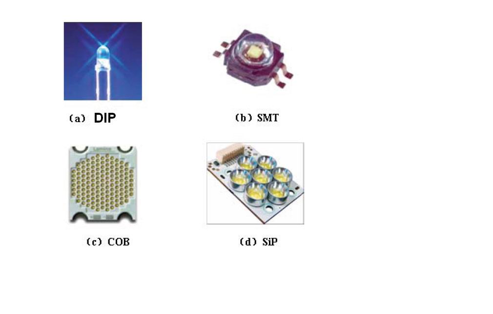
6, What is SMT? What is the SMD?
SMT is Surface Mounted Technology acronym, it’s a kind of technology and technique most popular on the electronic assembly industry’s. SMD is Surface mounted device acronym
7, what is LED display module?
To determined by circuit and installation of the basic unit, with display function. Through simply install to achieve the base unit function.
8, what is LED display screen ?
Through certain control method, the display screen is composed of LED array.
9, what is the inserted lamp module? What are the advantages and disadvantages?
Refers to the DIP package light the lamp foot through the PCB board, the tin filled in the lamp holes with welding, this technology module is call “inserted lamp module”; the advantages is: large visual angle, high brightness, good heat dissipation; disadvantage is the pixel density;
10, what is the Surface mount? What are the advantages and disadvantages?
Surface mount is also called the SMT, SMT package light through the welding process of welding on the surface of the PCB, the foot of lamp not through the PCB board, made by this process is called surface-mount module; advantages are: the perspective of large, display image soft, large pixel density, suitable for indoor viewing; drawback is that the brightness is not enough, the heat dissipation is not good enough;
11, what is the sub surface mount module? What are the advantages and disadvantages?
Sub surface mount is a product between DIP and SMT, the LED lamp package surface like SMT, but its positive and negative pin and DIP, production is through the PCB board to welding, the advantages are: high brightness, good display effect, the shortcoming is: complex process, difficult to repair;
12, What is the 3-in-1? What are the advantages and disadvantages?
Refers to the R, G, B three different colors of LED chip package in the same gel; advantages are: the production of simple, good display effect, the disadvantage is: spectrophotometric color difficult, high cost;
13, What is three and one? What are the advantages and disadvantages?
refers to the R, G, B three independent SMT package tied together in a certain light vertical spacing, so that not only has the 3-in-1 All individual advantages, but also to solve the shortcomings of 3-in-1;
The solution of LED display control card
LED display card is cord part of LED display part. LED display to show the variety of text, symbols and graphics 。 The content of display from a computer to edit, adoption of display control card to show the content via RS232/485 of computer. This LED display is mainly for the variety of text, symbols and graphics .first ,the information of display by computer to edit. Output the information into LED Screen memory via RS232/485 serial port。Then to display in circles. The mode of Display is rich and colorful, and display work offline. It’s flexible control, convenient operation, low cost, is widely used in various sectors of society.
Synchronous LED screen control card:
Synchronous LED control card, it’s mainly used to display real-time video, graphics, notification. is widely used in indoor or outdoor full-color large screen display.the work way is same Synchronous control system led LED display control card and computer monitor, it takes at least 60 frame / sec update rate corresponding to update the map image on a computer monitor, typically have the ability to display multiple shades of gray, it’s can be achieved multimedia advertising effect. Its main features are: real-time, enrich expressive, the operation is more complex, high price. A synchronous led display control card system in general by sending cards, reception cards, and DVI graphics cards. Synchronization led display control card.Asynchronous LED display control card is also called offline LED control card or offline card. It’s mainly used to display a variety of text, symbols and graphics or animation. Screen display information by computer editing, frame memory through the RS232/485 serial port implantation of LED display screen in advance, and then screen display, play in circles, display way is rich and colorful, diverse. Its main features are: simple operation, low price, wide application range. Simple asynchronous LED controller card can only display digital clock, text, special character. Graphic asynchronous LED control card function that has simple control system . the biggest feature is according the zone to control display screen. Support analog clock display, countdown, pictures, tables and animation display. With a timer switch, temperature control, humidity control and other functions.
Synchronous LED display control card:
The card of send To plan or arrange the show content according to a specified form and play order at VGA display. Other side the show contentAt VGA display will be send to control board through card of collect.Collect card is interface card using to connect of display card and LED screen.Receiving card can be receive video signal (control signal and data signal) from the sending card. the data of video signal through the data separation, the data field is stored in the external cache, then according to the zone to read, transmitted to the display screen.
Asynchronous LED controller card:
The computer Edited display data will be stored into LED display control card, does not affect the LED display after the shutdown of the computer. this system is asynchronous LED controller card.
About LED controller
LED controller used control of led switch by ic chip.
1, low voltage led products, large power controller
In general the design voltage of low voltage products as 12V-36V, the quantity for each loop of 3-6 in series . LED current limiting with the current limiting resistors, each loop current below 20mA . A LED products has a lot LED loop to composing. Advantage is low voltage, construction is simply , easy to design ; the shortcoming is: the current large when product size big, low voltage switching power supply need install. due to the limit of products disadvantage. The Low voltage con’t long-distance transmission. are confined to a small volume products, such as: text of signboard , small text pattern. According to the features, specification of product design: 12V choice of 75A/30V MOS to control, output current as 8A/channel; 24-32V choice of 60A/50V MOS to control, output current as 5A/chanle; Users can select the channel quantity of led controller, according to the above specifications, Note that the LED must be a common positive(+) pole connecting method, controller is common negative(-)pole, controller is not include low voltage source.
2, Low voltage LED in series controller
multi- control channel is mainly feature for The low voltage led in series controller. Used the transmission of in series single to realized a purpose of control . in general, 512 unit just only need to control of four control lines, the in series LED controller need to configuration of register at light source board of LED .
3, High voltage LED controller
The high voltage led controller is alternating voltage(AC). Echo circuit loop has 36-48 in series of LED, and echo current of circuit loop is 20mA below. There are has two kinds of current limiting mode, one is the resistor limiting current. The resistance power consumption is large in this mode, suggestion that echo of four resistors are connected in series with a 1/4W metal mold resistor. Uniform distribution of heat, this mode is most stable and reliable in currently. Other mode is the capacitance connected in resistance to limiting current. A lot of voltage drop across the capacitor at the connecting method. Resistance power is small. But it just only runs in stable of supply power. The capacitor energy is storage when the supply power is unsteadiness.Thereby LED easily damaged. Any used the controller to control the led with resistance limiting current is necessarily. Echo loop of led has one meter, and power 5W,three-color per meter 15W.
finally: attention should be paid to load matching! The light distribution of neon and LED’s are not the same, the same circuit can not be mixed with different types of load.
Music LED Lighting Controllers a work in progress
1,Design of Music LED Lighting Controllers
1.1,Theory of music lights rhythm display system
1.1.1,require analytics
When Design of a system, first know that the market demand, to ensure that do such a system is necessary ,second to determine the status of current market and the most recent scientific research to ensure the system of their own design is practical and advanced.
1.1.2 the analytics of system function
First we should be know the purpose and useful for any system. the music light display system is external lights along with music beat to display. For the application of systems is divided into three parts: input parts, mcu part and output part.Input parts refers to the music from the external input to the MCU process. MCU processing refers to deal with the input data with MCU, and for the output display part provides the necessary data and display the required basis. Output part refers to external lights along with music to flash. The designer can be decision of flash way of lights, the flash way has dynamic or static, or color or monochrome. We will talk about the concrete design of the three part:
1.1.3 Design of input part
Because of MCU just only deal with the disperse digital signal, but in real life is more analog signal especially music signal range as 200Hz to 15KHz, which is the practicality of the system to table a proposal and requests. To achieve of disperse of analog for input data. This is to be an easy job to the modulus is more and more mature conversion technology. That is to say we must through the analog-to-digital converter (ADC) converts the input music analog signal to digital, and then into the microcontroller.
1.1.4 MCU process
Input to MCU data stored in the microcontroller’s data store(MCU data memory). Because of display part ask the light flash along with music beat. But the music belongs to the audio signal. corresponding to the beat of the music and audio signal frequency, so in order to achieve unity displayed with the beat, it is necessary to discrete digital signal , digital signal processing technology and audio signal frequency is currently the most commonly used is the discrete Fourier transform(DFT).
1.1.5 output display part
Design idea is relatively simply and straightforward for output display part. which is easy to implement. Consider to the frequency range of the actual music signal is 200Hz ~ 15KHz,Through the A / D converter after, sampling the analog frequency will correspond to the digital frequency K value , i.e., a certain range of values K (where K the maximum value is carried out by DFT points). This system is realized by using different colors of the diode consists of a 5 x 7 dot matrix. With 7 diodes of different colors to represent different frequency, which the digital frequency value of K is divided into 7 equal parts, each segment of K value with diode represents a color. Each color diodes have 5 used to represent the amplitude, the amplitude is divided into 5 sections to achieve different. Because the signal amplitude of the MCU 5V maximum, when the range of 0 ~ 1V, the corresponding frequency diode light one; is 1 ~ 2V, bright two diodes; for 2 ~ 3V, bright three diodes; for 3 ~ 4V, bright four diodes; 4 ~ 5V, bright five diodes.
The above is a general idea of the topic(LED contrller),
COB LED product process
Chip On Board, COB
process is First using a thermal conductivity covering the wafer placed on surface of substrate (usually with the epoxy resin mixed with silver particles). Then the silicon wafer directly placed on the surface of the substrate, a silicon wafer is firmly fixed to the base with heat treatmen Final, create a electrization connection between the surface of substrate and silicon wafer with way of wire welding. Bare chip technology mainly has two forms: one is the COB technology, the other is the flip chip technology (Flip Chip).The board chip packaging (COB), a semiconductor chip connection mounted on the circuit print board, electrical connects in surface of substrate and chip whit suture method for lead. covered with resin to ensure reliability. Although COB is the most simple chip mounting technology, but the packaging desity if not as good as than TAB and a welding technology.
COB mainly welding method: (1) hot pressure welding
The metal wire and the welding pressure welding together by heat and pressure. Its principle is to add pressure and add heating, makes the welding zone to produce plastic deformation and destroy the oxidation layer of pressure welding on the interface,so that the inter atomic appeal to “bond” purposes, in addition, two metal uneven interface to add heating and add pressure can make mutually embedded compression and incrustation for the the top and bottom metal.This technique is generally used for chip on glass plate COG.
(2) for ultrasonic welding
Ultrasonic welding can be generated energy by ultrasonic generator,through the transducer in the ultra high frequency magnetic field induction,rapid expansion to generate elastic vibration, make a corresponding vibration for the chopper, driven the AI metal layer as the pad (AI film) rapid surface friction. Then the AI wire and AI membrane surface of the plastic deformation, the deformation and failure of the oxide layer, make the two pure metal surface in close contact to interatomic bonding, and come into being wedge. The main welding material for aluminum wire bonding.
(3) wire welding
Ball welding technology is the most representative welding technology in wire bonding. Because the semiconductor packaging and triode package use wire ball bonding welding. And it is convenient in operation, flexible, solid solid solder joint(AU wire diameter 25UM of weld strength is generally 0.07 ~ 0.09N / point) and no direction, the welding speed can be up to 15 point / sec. Wire bonding is also called thermal (pressure) sonic welding main bonding materials for gold (AU) wire welding, Having the shape of a sphere, also called the solder ball
The first step: expanding crystal。 Expansion machine will uniform expand the whole LED wafer thin film.the attachment of LED grains are closely arranged in a thin film on the surface opened, easy thorn crystal.
Step two: gum. The expansion of good crystal crystal ring put in gum machine(gum machine has been scraping silver layer), back silver paste. Point Silver. LED chip is suitable for bulk.(Dispenser)using the appropriate amount of silver paste on the PCB printed circuit board.
third step: the expanding ready Silver Crystal Ring crystal planes into the thorns,the operator used the microscope LED wafer crystal pen with barbed spines are on
The printed circuit board PCBunder the microscope the
fourth step: Put the thorn good crystal of PCB circuit print board into heat cycling constant temperature oven for a period of time. Wait for the silver slurry is solidified out(not for a long time, otherwise LED chip coating will be roasted yellow, oxidizing, difficult to bonding ). LED chip bonding is necessary above step, the IC chip bonding is not necessary above step.
fifth step: sticking chip. using the (Dispenser) place amount of Red glue on PCB the circuit print board IC position。Then put the IC into correct on red plastic or vinyl with anti-static devices (vacuum suction pen or sub).
The sixth step:drying. The good die stick need to constant temperature for a period of time on hot circulating oven big plane. Can also to naturally cure (but time is longer).
The seventh step: bonding(wire).connect of wire between the wafer (LED grain or IC chip) and PCB board corresponding to pad via aluminum wire bonder machine. This is wire of welding for COB.
eighth step: Pretest。 Using profession test tools(according to difference purpose to choice difference tools )to check out the COB board, will not be qualified to repair。
ninety step: dispensing。The dispenser will deploy a good amount of A B venue to the LED grain bonding, IC with black plastic package, then base on the require of customer will package.
tenth step: curing. The sealed plastic PCB printed circuit board placed in an oven heated to stand the heat cycle, the requirements can be set according to different drying times.
eleventh step: after the test. The packaged PCB printed circuit board with special tool for the detection of electrical performance test, to distinguish good or bad. compare of other technology of package, The COB technology price is low cost(just only for the same chip about 1/3), space saving, technology maturity However, any new technology can not be perfect at first appear,
The main difference between HID and halogen lamps
The main difference between HID and halogen lamps is,
Light by gas ionization luminescence for the former. Light through heated tungsten filament for the latter. Although they are same between the luminous arc xenon lamp and halogen lamp filament length, but the brightness luminous efficiency is improvement of three times for the HID. It’s haven’t use the filament, not the traditional lamp is ease to fracture. So service time up to 10 times. according to the text, a 35W HID light source can make a 55W halogen lamp 3 times light luminous. The service time as much as car lamp. So using halogen lamp can be save-energy. is represent the general trend that HID to replace halog lamp.
Comparison of HID gas discharge lamp and halogen bulb
Type The bulb wattage Color Service
—— lumen (W) Luminous temperature (K) time(HR)
HID 35 3200 6000 2500
H4 55 1000 3000 300
9006 55 1000 3000 250
H1 55 1500 3200 250
H7 55 1500 3200 250
The advantage of HID:
The halogen lamps light luminous system(filament) whit 12V dc voltage. Comparison of it, the HID does not using the filament, other advantage is that consumption of electricity only 50% tungsten halogen lamp. And it’s luminous is 3 times, and service life is five times the halogen lamps. Because the HID system just only consumption of electricity power only 36W,so it’s high efficiency and safety.
have the following characteristics:
1、three times output luminous.
Usually in the calculating the brightness of unit is usually called “Lumen” HID can be output the brightness up to 3200Lumen. While the halogen bulb can only be generated brightness on about 1000 Lumen. HID three times higher than traditional halogen lamp luminance efficiency,for the promotion of night and fog sight definition has the obvious the effect.
2, the color temperature is very comfortable
The so-called color temperature of light is a color temperature produce a light color, the lower the temperature, the color temperature will be close to red.Contrarily , will be close to bule, about 6000K light color just as white,
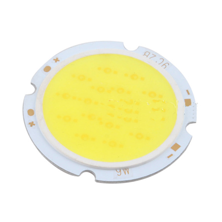
Acquaintance COB LED
Compared with the traditional lamp, the COB LEB lamp advantage is continuous improvement COB package technology is getting more and more recognition. Because of the COB LED lamp has some feature such as: low heat resistance. high flux density,less glare, light uniformity, so the LED COB has widely application in the LED market. such as: Lamp, bulb, fluorescent tubes, street lamps and mining lamp。In here we will description of COB LED lamp relatively advantage than the traditional LED package. Follow we will be put forward the five advantage: LOW heat resistance,Light quality, application advantage, cost advantage. The produce efficiency and produce flow is same basically,but COB LED is high efficiency than traditional smd led on Dispensing, separation, splitting, packaging. The SMD report states that 10 percent of the materiel cost to the laborage and produce cost. If use the COB LED to replace traditional SMD lamp, the worker ‘wage and produce cost will be save to 5 percent. The COB LED is low resistance package(surface light source),widely visual angle and adjust easily, reduce loss of light refraction, application advantage:forenamed the COB LED was quite wide of the market application. such as LED Light Tube ,high strip.At the sight of the data and note above, we can be knows that the save-cost range from 19% to 32% when with the COB LED to replace traditional SMD lamp, so The produce cost reduced their led market demands. The business rivals To become diminished.