LED as the display, due to its advantages of high luminous efficiency, long service life, easy to control.has increasingly been used in more fields Especially in now began to be widely used in the lighting system of city / stage。This paper describes the types of LED lights, LED lighting control dedicated chips, the hardware and software design ideas design ideas .Color image point: in order to make the LED light color display is required by at least two or more different LED colors form a LED pixels. RGB LED collocation according to the brightness and gray level demand can have a variety of combinations, such as: 1 pcs red LED + 1 pcs green LED+1 pcs blue LED can be display 256 gray color. The LPD6803 is specially designed for LED lighting system driver chip, built-in-PWM, can generate three-way constant current driving and gray adjust output.
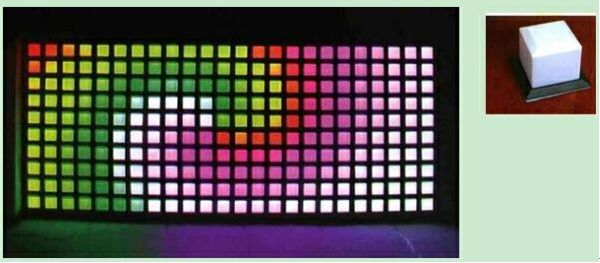
Technical features:The multi- color pixel dot composed of led tube. each pixel changes can be independently produced 256 color.
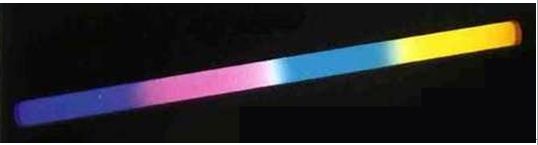
Application environment: overpass, river fence, decorative lighting of building exterior wall in different places.Multi-color pixel dot compose of a module. Can be independent controlled of echo pixel dot.
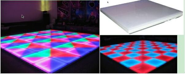
Application environment: bar, KTV, stage. As decorative lighting floor or walls.LED lighting control chip introduced LPD6803 is designed for LED lighting driver chip, simple control.
Function description:
The built-inA. oscillator,The scan does not need that the control board to provide scan clock.The B. two control lines, control and simple wiring.C. data clock can reach 25MHz, you can get more cascaded output.LED lighting control system hardware design ideas
LED lighting control system mainly consists of the pixel drive unit and control panel designed in two parts.
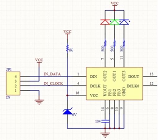
The 1 display unit design of the driving point How to achieve the pixels showing a different color, mainly rely on the principle of human visual intermittent inert,using each pixel to produce different duty cycle for the mixing of colors. The design of LED color display case mainly depends on the LPD6803 automatic output 3 channel 256 gray color to achieve color display. The controller only needs to transmit each pixel scanning duty cycle data .
The drive unit design diagram below, suitable for color LED guardrail tube, LED floor tile applications.
the number of red, green and blue three-color LED can be multiple. Single LED cascade mode can be used in series or parallel way to achieve, in the design is you need to The hardware is only provided the design of a control system for your reference, To be sufficient some basic conditions needed for an ordinary LED lighting system.According to the actual system, can choose ARM, CPLD, accelerate the speed of transmission data and USB communication, SD card storage requirements.Hardware design of objective description(consider the voltage / current and external drive. Data output cascade connect to the next module input will achieve a cascade system.
Hardware design of objective description
U1: use MCU51 microcontroller, if the system drive pixel cascade number not much and don’t need to do image animation too complex display case. The MCU even can choose 2051 pin low, low price of MCU.
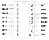
JP1: with LPD6803 serial sequence interface for output, only DATA, CLOCK, GND can meet the requirements of data transmission.
U4: SPI FLASH, for storing program data. According to the need of the system can be used to design multi chip FLASH memory chip. SPI FLASH now relatively high capacity can be done 4M bits.
U6: as the communication interface, used to show content and transmitting program data system host communication control. And for the upgrade program.
Driven design software 3
The following to drive the individual pixels to illustrate the data transfer mode. LPD6803 is an automatically generated 128 level!